The following is from a previous reply on this post.
It should answer your question.
I have PCB REV A 20220402
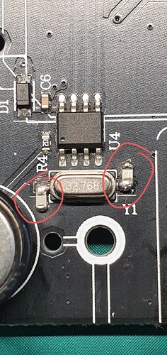
The correct way to modify the circuit is like this. Loading capacitors and crystal should be mounted as close the RTC IC (U4) as possible with symmetrical PCB track length. Clean a small amount of the black solder mask on the ground plane with a fiber pencil or modeling knife to expose the copper without damaging the copper surface too much. Carefully solder the two smd 8pf capacitors as I have shown in the picture. These PCB’s would(should) have used lead free solder but I would suggest to rework using leaded low temperature solder. Clean any flux residue with alcohol or similar to avoid any chance of electrical leakage. This did drop my clock frequency very slightly as expected but not enough to worry about, the device will occasionally re-synchronise the time over WiFi to keep it accurate (at least it should!). Also check the 5.5v back up cell (EC1) it should read approx 4.7v when the unit is plugged in, it won’t stop the RTC working or give the time-error but you will loose the time if it fails when the unit is unplugged. These cells don’t last much more than 6-8 years. Be sure to work on an anti static mat and take all the usual static precautions.