I am showing the location and the challenge that you will have to appropriately add the 8 pfd ceramic capacitors.
Thanks James. If you’ve added the component please post a photo. ![]()
![]()

My unit is very intermittent but I noticed it failed regularly with higher humidity so Role could well have the answer, the data sheet indicates these capacitors are required and unless the HT1381 has internal loading capacitors, which I doubt, they should definatly be fitted.
I have PCB REV A 20220402
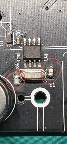
The correct way to modify the circuit is like this. Loading capacitors and crystal should be mounted as close the RTC IC (U4) as possible with symmetrical PCB track length. Clean a small amount of the black solder mask on the ground plane with a fiber pencil or modeling knife to expose the copper without damaging the copper surface too much. Carefully solder the two smd 8pf capacitors as I have shown in the picture. These PCB’s would(should) have used lead free solder but I would suggest to rework using leaded low temperature solder. Clean any flux residue with alcohol or similar to avoid any chance of electrical leakage. This did drop my clock frequency very slightly as expected but not enough to worry about, the device will occasionally re-synchronise the time over WiFi to keep it accurate (at least it should!). Also check the 5.5v back up cell (EC1) it should read approx 4.7v when the unit is plugged in, it won’t stop the RTC working or give the time-error but you will loose the time if it fails when the unit is unplugged. These cells don’t last much more than 6-8 years. Be sure to work on an anti static mat and take all the usual static precautions.
I should know in the next couple of weeks if this modification has fixed the issue.
Clearly this is going to be outside the scope of most people on this forum, but if you know a capable friend with the required tools it is quite simple.
1 Like
I’m awaiting your feedback on the modification. It would be very helpful if someone could share step-by-step pictures showing the ‘before’ and ‘after’ views side by side, as I don’t have an electronics background. I plan to get this done at a soldering shop, so detailed pictures would help me explain the work clearly.
This post does contain sufficient detailed information to understand the issue and what steps to take to stabilise units that have issues.
Some electronics back ground will help.
Just to confirm, adding the additional capacitors has fixed the problem with my controller. I did find a deal to get a new IIC-800 and had a look at the PCB. The new products have the capacitors added in the same manor as I did with mine. So it would appear that issue has been resolved. You will need the correct size of capacitor so they fit neatly, search using the following sentence, I buy mine from AliExpress.
0603 SMD capacitor 8pF
Hi. Do you have a picture of the repair you did?
Instead of soldering to the pins of the U4 integrated circuit, couldn’t you solder to the crystal pins and connect them to the PCB ground? That way I wouldn’t have to solder to U4.
I have the same board as you.
Thanks, Alejandro
Hello. I have an 8.2 pF capacitor, would that work too?
Solder the capacitors as close to the crystal as possible as you can see in my photo. 8.2pf capacitors will be okay.
The following is from a previous reply on this post.
It should answer your question.
I have PCB REV A 20220402
The correct way to modify the circuit is like this. Loading capacitors and crystal should be mounted as close the RTC IC (U4) as possible with symmetrical PCB track length. Clean a small amount of the black solder mask on the ground plane with a fiber pencil or modeling knife to expose the copper without damaging the copper surface too much. Carefully solder the two smd 8pf capacitors as I have shown in the picture. These PCB’s would(should) have used lead free solder but I would suggest to rework using leaded low temperature solder. Clean any flux residue with alcohol or similar to avoid any chance of electrical leakage. This did drop my clock frequency very slightly as expected but not enough to worry about, the device will occasionally re-synchronise the time over WiFi to keep it accurate (at least it should!). Also check the 5.5v back up cell (EC1) it should read approx 4.7v when the unit is plugged in, it won’t stop the RTC working or give the time-error but you will loose the time if it fails when the unit is unplugged. These cells don’t last much more than 6-8 years. Be sure to work on an anti static mat and take all the usual static precautions.
1 Like
Hello. Good morning.
I had ordered SMD capacitors, but they sent me the ones that use PCB holes.
Well, I think I managed it. I’m sending you photos. I hope they’re useful.
Thank you very much, Alejandro Castelli


That should be ok and do the trick. Well done!
901
Hello. Here’s a controller that was replaced with the previous one after it failed while under warranty.
This one developed a clock error at a country house after working for a little over a year. I brought it to my city house and, before adding the capacitors, I left it connected for several days, and the clock error didn’t recur.
However, I disassembled it and noticed it has a different PCB. I don’t think the oscillator has the 8 pF capacitors either, or I can’t see them and they’re in a different part of the circuit. It’s a very small oscillator.
Why is the problem more noticeable in one house than another? Could it be related to the quality of the electricity in the area?
I remember that the other model I repaired also took a while to develop the problem when I tested it at my city house.
Thanks. I hope this is clear.
Thanks, Alejandro


Humidity and temperature differences will affect the behaviour, I had the same problem.
However the capacitors are missing on this PCB version. I would suggest adding them.
It is my understanding that the Rev A board which this is has the IC that requires the 8 pfd capacitors to provide Oscillator stabilisation.
As to why different environments cause the controller to display more failures than others is not apparent.
I can only say that the capacitors has fixed my problem.
Cheers
Robin Guy
RobinGuy@internode.on.net
MB: 0413054387
Hello, for now it’s working without a clock error.
The only problem is that when I turn it off, disconnect the power, and then reconnect the power, it goes back to operating in the “on” state.
The rest of the zone and irrigation settings are unaffected.
Is there any way to fix this problem?
Your problem would not be related to the hardware issue we have resolved in this post. The device default configuration would probably restart to the ‘ON’ mode in case of power cuts.
On the assumption that the “On State” you mean that it returns to the pre programmed automatic watering cycle state and that you want it to remain off for some reason then you will need an additional WIFI mains power 240 volt Switching device.
A device like the EWeLink or Tyua power switch will on power failure recover to the “Off State”. Use this in conjunction with the Inkbird IIC- 800- WIFI controller.
Hope this helps!
I am experiencing the same problem with 1 of my 2 controllers. Mine is the later one shown above (Rev A 20230202). With that particular SMD crystal (T319B), it looks extremely difficult to get at the 2 solder points under the crystal to connect capacitors. Has anyone successfully done it? Any tips, or photos?
I’ve submitted a ticket to support, but I’m 6 days past the 2 year warranty, so we’ll see if they honour that. Might have to be soldering!
